
How can one select ball size in ball milling and how much
More balls with small size results in fine powder. As a thumb rule powder to be milled should be taken as 25% of total ball weight. If the quantity of charge is very less then milling balls will
 WhatsAppGet PriceGet A Quote
Metallurgist & Mineral Processing Engineer
The Bond_Mill Sizing spreadsheet was designed to determine the most appropriate mill dimensions and operating conditions for a given grinding task (known ore properties plus desired mill throughput and feed and product sizes), based on the traditional Bond''s Law and the Hogg & Fuersteneau Power Model (see Mill Power_Ball Mills spreadsheet for
WhatsAppGet PriceGet A Quote
3 easy steps to calculate ball mill capacity
Step 2. Ball mill drum dimensions. Specify the length and capacity of the drum. If not available, specify the length and diameter of the drum. Step 3 (the final). Grinding bodies. Specify the weight of grinding bodies. You can simply specify a fill ratio for the drum if you do not know the exact weight of grinding bodies. Done!
WhatsAppGet PriceGet A Quote
Addition of pebbles to a ball-mill to improve grinding
Each pebble feed size produces a steady-state distribution, analogous to the ball-mill calculation. A spreadsheet was used to accumulate weighted data for all feed pebble sizes. This method makes the simplifying assumption that the pebble wear rate is independent of pebble size.
WhatsAppGet PriceGet A Quote
EFFECT OF BALL SIZE DISTRIBUTION ON MILLING PARAMETERS
2.4 Effect of ball size 29 2.4.1 Empirical approaches 29 2.4.2 Probabilistic approaches 33 2.5 Abnormal breakage 36 2.6 Effect of ball mixture 37 2.6.1 Ball size distribution in tumbling mills 37 2.6.2 Milling performance of a ball size distribution 40 2.7 Summary 41 Chapter 3 Experimental equipment and programme 43
WhatsAppGet PriceGet A Quote
Spur Gear Calculator
Ball Mill Finish Calculator. G & M Code Characters. Standard End Mill Sizes. Standard Drill Sizes. Spur Gear Calculator. Number of Teeth. Diametric Pitch. Pitch Diameter.
WhatsAppGet PriceGet A Quote
How can one select ball size in ball milling and how much
More balls with small size results in fine powder. As a thumb rule powder to be milled should be taken as 25% of total ball weight. If the quantity of charge is very less then milling balls will
WhatsAppGet PriceGet A Quote
Metallurgist & Mineral Processing Engineer
The Bond_Mill Sizing spreadsheet was designed to determine the most appropriate mill dimensions and operating conditions for a given grinding task (known ore properties plus desired mill throughput and feed and product sizes), based on the traditional Bond''s Law and the Hogg & Fuersteneau Power Model (see Mill Power_Ball Mills spreadsheet for
WhatsAppGet PriceGet A Quote
Ball mill media optimization
(“Ball mill classification system optimization through functional performance modeling,” Nov. 17, McIvor et al., 2017, Mining Engineering) described circuit classification system efficiency (CSE), equal to the percentage of coarse (plus circuit P80 target size) material in the ball mill. It can be measured and then increased through
WhatsAppGet PriceGet A Quote
Engineering Spreadsheets & Presentations [Archive
MDT & XPT Pressure Plotting Software/Spreadsheet. API 5l Gr. X and ISO 3183. Presentations - DeWatering with ESP / Presentations - Rod Pumping Gas Wells. Electrical Design Spreadsheets. how to calculate I-BEAM. Blind Flange Design. Tank Breather Valve. Free Applications & Scripts for Petroleum (Oil & Gas) activities.
WhatsAppGet PriceGet A Quote
SPECIFIC COMMINUTION ENERGY
= Bond laboratory ball work index (kWh/tonne) P. 1 = closing screen size in microns . Gbp = net grams of screen undersize per mill revolution . P = 80% passing size of the product in microns . F = 80% passing size of the feed in microns . Circuit Equipment Configurations – Although the model can be used for a very wide range of
WhatsAppGet PriceGet A Quote
EFFECT OF BALL SIZE DISTRIBUTION ON MILLING PARAMETERS
2.4 Effect of ball size 29 2.4.1 Empirical approaches 29 2.4.2 Probabilistic approaches 33 2.5 Abnormal breakage 36 2.6 Effect of ball mixture 37 2.6.1 Ball size distribution in tumbling mills 37 2.6.2 Milling performance of a ball size distribution 40 2.7 Summary 41 Chapter 3 Experimental equipment and programme 43
WhatsAppGet PriceGet A Quote
Chapter
2.1 SAG mill modeling In MODSIM, one of the simulation models used for a SAG mill unit is SAGT (Semi-Autogenous Grinding with Trommel) model. In this model, a SAG mill with a trommel screen at mill discharge is modeled using the full population balance including particle attrition and wear (King 2001b). In this
WhatsAppGet PriceGet A Quote
Speed feed calculator
If you need a calculator file in native Open Office format, send me an email (see Contacts page). Here’s a neat speed and feed calculator, courtesy of Burny Kaliburn.
WhatsAppGet PriceGet A Quote
Media Charge_Ball Size _ Density.xlsx
View Media Charge_Ball Size _ Density.xlsx from ECON ECON515 at Oxford University. Moly-Cop Tools, Version 3.0 About the Media Charge_Ball Size & Density Spreadsheet .
WhatsAppGet PriceGet A Quote
AMIT 135: Lesson 7 Ball Mills & Circuits – Mining Mill
Number, size and mass of each ball size depends on mill load and whether or not the media is being added as the initial charge. For the initial chargin of a mill, Coghill and DeVaney (1937) defined the ball size as a function of the top size of the feed, i.e., d↓V = 0.40 K√F dB = ball size (cm) F = feed size (cm)
WhatsAppGet PriceGet A QuoteBall Mill Parameter Selection & Calculation
1 Calculation of ball mill capacity. The production capacity of the ball mill is determined by the amount of material required to be ground, and it must have a certain margin when designing and selecting. There are many factors affecting the production capacity of the ball mill, in addition to the nature of the material (grain size, hardness
WhatsAppGet PriceGet A Quote
Grinding Mill Computer Model
sizing and tonnage. 3.5 Pebble Mill Design This reverts to the Morgärdshammar method and is similar to the AM calculation 3.6 Tower Mill The tower mill calculation is based on the ball mill design sheet, but is simplified in that the mill design section is omitted. A simple tower mill factor of 70% allows the mill power to be estimated.
WhatsAppGet PriceGet A Quote
3 easy steps to calculate ball mill capacity
Step 2. Ball mill drum dimensions. Specify the length and capacity of the drum. If not available, specify the length and diameter of the drum. Step 3 (the final). Grinding bodies. Specify the weight of grinding bodies. You can simply specify a fill ratio for the drum if you do not know the exact weight of grinding bodies. Done!
WhatsAppGet PriceGet A Quote
Ball Mill Costing Calculation
ball mill sizing calculation spredsheet,ball grinding machine sizing calculation spredsheet Time:2014-03-25 ID:11744 Related news and images with ball mill sizing
WhatsAppGet PriceGet A Quote
Grinding Mill Computer Model
sizing and tonnage. 3.5 Pebble Mill Design This reverts to the Morgärdshammar method and is similar to the AM calculation 3.6 Tower Mill The tower mill calculation is based on the ball mill design sheet, but is simplified in that the mill design section is omitted. A simple tower mill factor of 70% allows the mill power to be estimated.
WhatsAppGet PriceGet A Quote
Chapter
2.1 SAG mill modeling In MODSIM, one of the simulation models used for a SAG mill unit is SAGT (Semi-Autogenous Grinding with Trommel) model. In this model, a SAG mill with a trommel screen at mill discharge is modeled using the full population balance including particle attrition and wear (King 2001b). In this
WhatsAppGet PriceGet A Quote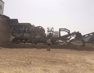
Formula Calculators
View Calculator. T a T a = Torque to accelerate (ft.-lbs.) W K2 W K 2 = Rotational inertia of object (lbs.- f t.2 f t. 2) (for solid screw shaft, use W K2 W K 2 = 1/8 W D2 W D 2. where W = weight of screw (lbs.) D = diameter of screw (ft.)) ΔRP M Δ R P M = Change in rotational speed (rpm)
WhatsAppGet PriceGet A Quote
Basic Cyclone Design
sample calculation particle size range particle size fractional efficiencies (microns) distribution d50 collection collected particulate min max (% by weight) (microns) (% by weight) (% by weight) 0 5 3 2.5 25.96 0.78 5 10 5 7.5 94.83 4.74 10 20 12 15 98.79 11.85 20 30 19 25 99.28 18.86 30 40 13 35 99.87 12.98 40 50 12 45 99.94 11.99
WhatsAppGet PriceGet A Quote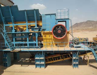
Addition of pebbles to a ball-mill to improve grinding
Each pebble feed size produces a steady-state distribution, analogous to the ball-mill calculation. A spreadsheet was used to accumulate weighted data for all feed pebble sizes. This method makes the simplifying assumption that the pebble wear rate is independent of pebble size.
WhatsAppGet PriceGet A Quote
Pontificia Universidad ólica de Chile
The Bond_Mill Sizing spreadsheet was designed to determine the most appropriate mill dimensions and operating conditions for a given grinding task (known ore properties plus desired mill throughput and feed and product sizes), based on the traditional Bond''s Law and the Hogg & Fuersteneau Power Model (see Mill Power_Ball Mills spreadsheet for
WhatsAppGet PriceGet A Quote
Ball Mill Design/Power Calculation
The basic parameters used in ball mill design (power calculations), rod mill or any tumbling mill sizing are; material to be ground, characteristics, Bond Work Index, bulk density, specific density, desired mill tonnage capacity DTPH, operating % solids or pulp density, feed size as F80 and maximum ‘chunk size’, product size as P80 and maximum and finally the type of circuit open/closed
WhatsAppGet PriceGet A Quote-
Pontificia Universidad ólica de Chile
The Bond_Mill Sizing spreadsheet was designed to determine the most appropriate mill dimensions and operating conditions for a given grinding task (known ore properties plus desired mill throughput and feed and product sizes), based on the traditional Bond''s Law and the Hogg & Fuersteneau Power Model (see Mill Power_Ball Mills spreadsheet for
WhatsAppGet PriceGet A Quote 
NTN Bearing Technical Calculation Tool Usage Method
NTN Bearing Technical Calculation Tool Usage Method 4/62 1-2. Screen flowchart On-screen processing for each window is displayed in Fig. 1. Fig. 1. Screen transition between each window Basic rating life Gear load and basic rating life Bearing load and basic rating life Operating clearance calculation Bearing vibration frequency TOP menu
WhatsAppGet PriceGet A Quote
Machining Solutions
NOTE: If the operation is not a full circle interpolation, simply input into the "Circle Diameter" data cell what the theoretical circle size would be. EXAMPLE: A 1.00 inch diameter end mill cuts an internal 90 degree corner that has a .625 inch radius.
WhatsAppGet PriceGet A Quote


 Mecca 500TPH Granite Crushing Plant